SharpDevelop + OpenTK Tutorial
Part 3: It's Time To Draw
Stage 1 - Deja Vu
Just like at the beginning of Part 2, re-open your project, and click on the Source tab. Your source will now be open.
Stage 2 - Frame Function
The first few stages of Part 3 will help you to create a function which will be used to draw onto your GLControl.
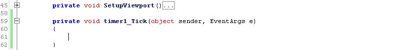
Begin by creating another function within the MainForm class. Just like the SetupViewport function, you will want to make this function private to the class, and void, since it will not be returning data.
Since this new function will be called by an event, you'll need to create some arguments. Call the function whatever you want to (I have called mine "timer1_Tick"), but the arguments must be specified as in the image below, within the brackets:
Stage 3 - Frame Rate
Before you fill your new function with drawing code, you will first need to "call" it. In order to call the function at regular intervals, you will need to create a timer.
One of the places you can set up the timer is the MainForm function, which is itself called once when the program is opened.
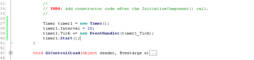
The following is an explanation of the above code:
The first line creates a new Timer object called "timer1".
An interval of 20ms is applied to timer1. This should result in a framerate of 50 Frames Per Second (FPS). Larger values will result in a lower FPS, suitable for slower computers. Smaller values will result in a higher FPS, suitable for faster computers. For the love of everything you hold sacred, DO NOT use and interval of 0! Your CPU will melt, and a plague of ravenous tigers will rain down from the sky.
The third line tells timer1 what to do when the 20ms interval has elapsed. If you have called your timer function anything other than "timer1_Tick", you will need to type that name into the EventHandler function call. This will ensure that the correct function is called, and your polygons are drawn to the screen.
The fourth line tells timer1 to begin "ticking". You won't hear a ticking noise, but the function will be called every 20ms (or whichever interval you have specified), making animation possible.
Stage 4 - The Concept of 3D
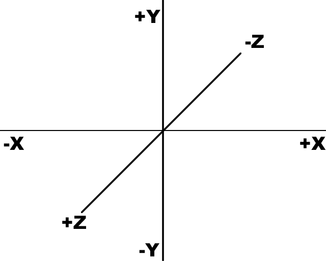
If you are an experienced 3D programmer, please skip to the next stage.Imagine your screen is a grid of coordinates. The centre of the screen is the origin (the place where X and Y coordinates are both 0). If you move to the left of the origin, the X coordinate decreases, but if you move to the right, the X coordinate increases. If you move down from the origin, the Y coordinate decreases, but if you move up from the origin, the Y coordinate increases.
Note that many other programming languages and development kits decrease the Y coordinate as you move up the screen, and increase it as you move down the screen. If you are used to this, please bear in mind that OpenGL may flip your graphics upside down if you forget this detail.
When developing 3D graphics, the third dimension comes into play. This is represented by the Z coordinate. In OpenGL, moving into the screen reduces the Z coordinate, and moving out of the screen increases the Z coordinate.
Now imagine that we draw a cube around the origin.
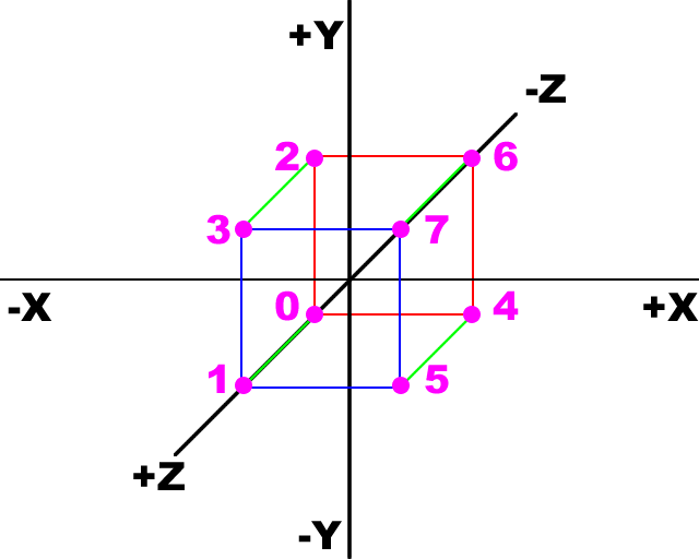
For the purposes of programming, I have numbered each corner. In the above images, the corners linked by a red square are behind the origin, and the corners linked by a blue square are in front of the origin. Using the above rules, the coordinates are listed below:
| Corner | X | Y | Z |
|---|
| 0 | -1 | -1 | -1 |
| 1 | -1 | -1 | 1 |
| 2 | -1 | 1 | -1 |
| 3 | -1 | 1 | 1 |
| 4 | 1 | -1 | -1 |
| 5 | 1 | -1 | 1 |
| 6 | 1 | 1 | -1 |
| 7 | 1 | 1 | 1 |
As most of you will know, a cube is made of 6 square faces, each with 4 corners - but that would make a total of 24 corners! In order to save the processor from calculating each point 3 times, we can reference each corner using an Array of Arrays (an Array is a technical term for a list). Each face, viewed from the outside, has the following points, listed clockwise:
| Face | C0 | C1 | C2 | C3 |
|---|
| Front | 1 | 3 | 7 | 5 |
| Back | 0 | 4 | 6 | 2 |
| Left | 0 | 2 | 3 | 1 |
| Right | 4 | 5 | 7 | 6 |
| Top | 2 | 6 | 7 | 3 |
| Bottom | 0 | 1 | 5 | 4 |
If you're looking at the diagram, and thinking that the corners listed for a face are anti-clockwise, this is because the face is being viewed from behind - there is a reason for this, which we will explore in Part 4 when we get up to drawing polygons. Before we can do that, we must first learn how to create a wire-frame. The first step toward doing that will be to convert the coordinates and the face lists into programming code.
Stage 5 - Corners and Faces
Now that we all understand the basics of 3D geometry, it is time to write these coordinates and references as arrays in the MainForm Class definition:

Apart from using different data types, I have created 2 different types of arrays. The corners are stored in a rectangular array, which is a technical term for a list of lists, each of equal length. Each of the arrays stored within the main array have a length of 3 values.
On the other hand, the faces are stored in a jagged array, which is a technical term for a list of lists, each of varying length. In this case, the length of the arrays within the main array are all the same, but if we wanted to define a more complicated shape, such as an icosidodecahedron, we would want some of the faces to have more corners than others.
Part 3 continues soon!
1 | 2 | 3 | 4 | 5
Part 4 coming soon!