Connectivity Mode
Introduction
The Barcode Battler II features a hidden "connectivity mode" which may be used for the sole purpose of turning the machine into a simple barcode reader.
To enable this mode, follow these steps:
Remove the tab from the left of the Barcode Battler II, towards the rear of the device.
Insert either a mono or stereo 3.5mm plug. IMPORTANT! If you are using a stereo plug, do not insert it as far as it will go! Connectivity mode works best when the stereo plug is 1mm or 2mm away from full insertion. A mono plug can be inserted all the way without a problem.
Insert the other end of the cable into a compatible device. This could be a Famicom, Super Famicom, Barcode Battler II2 C0 or a PC with a standard 3.5mm line-in or microphone socket.
Turn the Barcode Battler II off if it is already on.
Press and hold the R-BATTLE and R-POWER buttons together. Keep them held down and turn on the Barcode Battler II.
Release the R-BATTLE and R-POWER buttons. Connectivity mode will now be active.
Signal Format
The diagram below is an example of the signal sent out by the Barcode Battler II when the "Jaw Breaker" card is scanned:
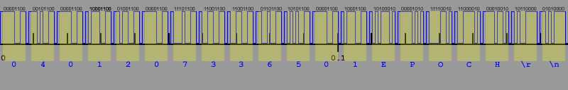
The transmission duration for the output signal is 0.168 seconds.
The signal levels are:
Binary "0" = High
Binary "1" = Low
The transmission can be broken down into 20 bytes, arranged as follows:
EAN 13:
13 bytes describing the barcode data
5 bytes which spell "EPOCH"
1 byte signalling "CR" (Carriage Return)
1 byte signalling "LF" (Line Feed)
EAN 8:
5 bytes signalling a "space" (hex 20)
8 bytes describing the barcode data
5 bytes which spell "EPOCH"
1 byte signalling "CR" (Carriage Return)
1 byte signalling "LF" (Line Feed)
Barcode read errors:
5 bytes which spell "ERROR"
8 bytes signalling a "space" (hex 20)
5 bytes which spell "EPOCH"
1 byte signalling "CR" (Carriage Return)
1 byte signalling "LF" (Line Feed)
Each data byte is preceeded by a 1-bit long High signal (a binary "0").
Each data byte uses ASCII encoding.
Each data byte is transmitted in reverse, with the least significant bit sent first and the most significant bit sent last.
Each data byte is followed by a 1-bit long Low signal (a binary "1").
The transmission ends with a continuous Low signal (binary "1").
The transmission contains 200 bits of data (including the seperators).
The duration of a single bit is 0.00084 seconds.
The duration of an 8-bit byte is 0.00672 seconds.
The duration of an 8-bit byte + seperator bits is 0.0084 seconds.
Knowing this, it is possible to decode the signal coming out of a Barcode Battler 2 in connectivity mode, and also to simulate the signal for use with the
connectivity games for the Famicom and Super Famicom.
Famicom Connectivity
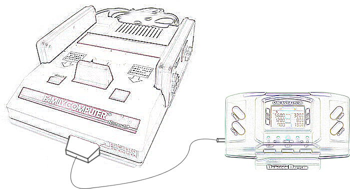
A special cable connects the Barcode Battler II to the 15 pin peripheral port on the front of the Famicom. This port does not exist on the NES.
The Ground connection, Pin 1 at the Famicom end, connects to the sheath of the 3.5mm plug at the Barcode Battler end. The data connection, Pin 6 at the Famicom end, connects to the tip of the 3.5mm plug at the Barcode Battler end.
The games which use the Barcode Battler connection on the Famicom can read the output of the Barcode Battler in connectivity mode directly.
Since we don't have a Famicom in our collection, the following image is an artist's impression of what the connection would look like. Our bad artist forgot to draw a game in the Famicom cartridge slot.
We are looking into modifying a TriStar NOAC device to accept this form of connection. There are some undocumented connections on the NOAC's pinout, one of which we hope correlates to Pin 6 on the Famicom's 15 pin port.
Super Famicom Connectivity
The Barcode Battler II Interface is a device which connects the Barcode Battler II to the Player 2 Controller socket of the Super Famicom.
The Barcode Battler II cannot be used as a controller in this configuration - it is simply a data input device.

Barcode Battler II2 C0 Connectivity
The Barcode Battler II2 C0 (BCBII2 C0) has no barcode reader of its own. It must be connected to a Barcode Battler II in order to function.
Since the BCBII2 C0 has two 3.5mm sockets, it is possible to link a second BCBII2 C0 to the Barcode Battler II using a "daisy chain" configuration. Due to the programming of the BCBII2 C0, it is not possible to use more than two of them at the same time with a single Barcode Battler II.
A rough diagram will be available soon.